Carrier Setup UL
This topic applies to uplink carrier configurations when Capability is set to Waveform Playback.
Save to 89600 Setup File
This feature saves the Carrier configuration as a 89600B VSA setup file, simplifying VSA configuration so you can quickly demodulate the signal. For information about setup file settings, refer to 89600 Setup File Setting.
Full-filled Config
Opens the Full-filled Configuration dialog window.
UL FRC Config
Opens the Uplink FRC Configuration dialog window.
Common UL Config
Opens the Common Uplink Configuration dialog window.
PUCCH Test Config
Opens the Common Uplink Configuration dialog window.
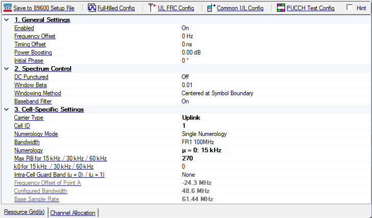
1. General Settings
Enabled
Default: On
2. Spectrum Control
DC Punctured
Choices: On | Off
Default: Off
Set whether DC is punctured in the final signal for current carrier.
For uplink carrier with Transform Precoding enabled for UL-SCH, DC Punctured is forced to Off.
3. Cell-Specific Settings
Carrier Type
Default:
Cell ID
Range: 0 to 1007
Default: 0
Set the cell ID for the carrier.
Numerology Mode
Default: Single Numerology
Bandwidth
Choices: Based on the Table 5.3.2-1 and 5.3.2-2 in 38.104.
Default: FR1 100M
Select the Bandwidth configuration for the carrier.
Numerology
Choices: u = 0: 15 kHz | u = 1: 30 kHz | u = 2: 60 kHz Normal CP | u = 2: 60 kHz Extended CP for FR1; u = 2: 60 kHz Normal CP | u = 2: 60 kHz Extended CP | u = 3: 120 kHz | u = 4: 240 kHz for FR2.
Default: µ = 1: 30 kHz
Select the numerology for current carrier in Single Numerology mode.
Max RB for 15 kHz / 30 kHz / 60 kHz
Range: Related to the numerology.
Default: 273
Set the maximum number of RB for current numerology of the carrier in Single Numerology mode.
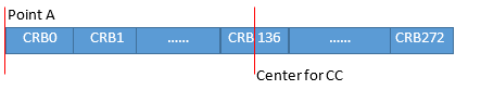
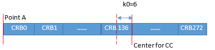
k0 for 15 kHz / 30 kHz / 60 kHz
Range: -6, 0, 6
Default: 0
Set the k0 for current numerology of the carrier in Single Numerology mode. It is used to adjust the center of carrier.
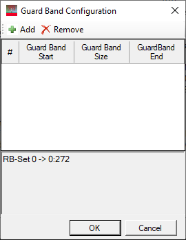
Intra-Cell Guard Band (u = 0) / (u=1)
Range: Depends on the size of current resource grid.
Default: None.
Couplings: This parameter is only visible when the 15 kHz/30 kHz numerology is enabled
Enter a comma-separated string to set guard band. For every two values, the first/second is the CRB start/CRB number of a guard band between two RB sets. There are 4 guard bands at most.
You can also click the  to open the
  Guard Band Configuration editor.
Frequency Offset of Point A
Display the relative location of Point A (in Hz) from the middle of carrier.
Configured Bandwidth
Display the occupied bandwidth of the carrier. It is calculated by the maximum bandwidth between each enabled numerology.
Base Sample Rate
Display the base sample rate of the carrier. It is a suitable sample rate for the current carrier.